Retro handheld : Minimalist game console
A STM32 board equipped with a mini OLED screen and a BLE Xbox Controller to recreate some old memories...
I was looking for a project idea to test my new NUCLEO-WB55 evaluation board when my eyes landed on a Xbox controller lying on my desk. This controller can connect remotely to a device via a proprietary 5 GHz protocol requiring a USB adapter or by the famous protocol: BLE (Bluetooth Low Energy). I also remembered having a small unused OLED display screen in my stock, originally bought for my Bus Tracker project. I thought it could be a nice occasion to also test this screen.
If you want to learn more about my Bus Tracker project, you can read more about it here.
Those mini-screens reminded me of the cheap mini handheld game consoles which were popular when I was a child.
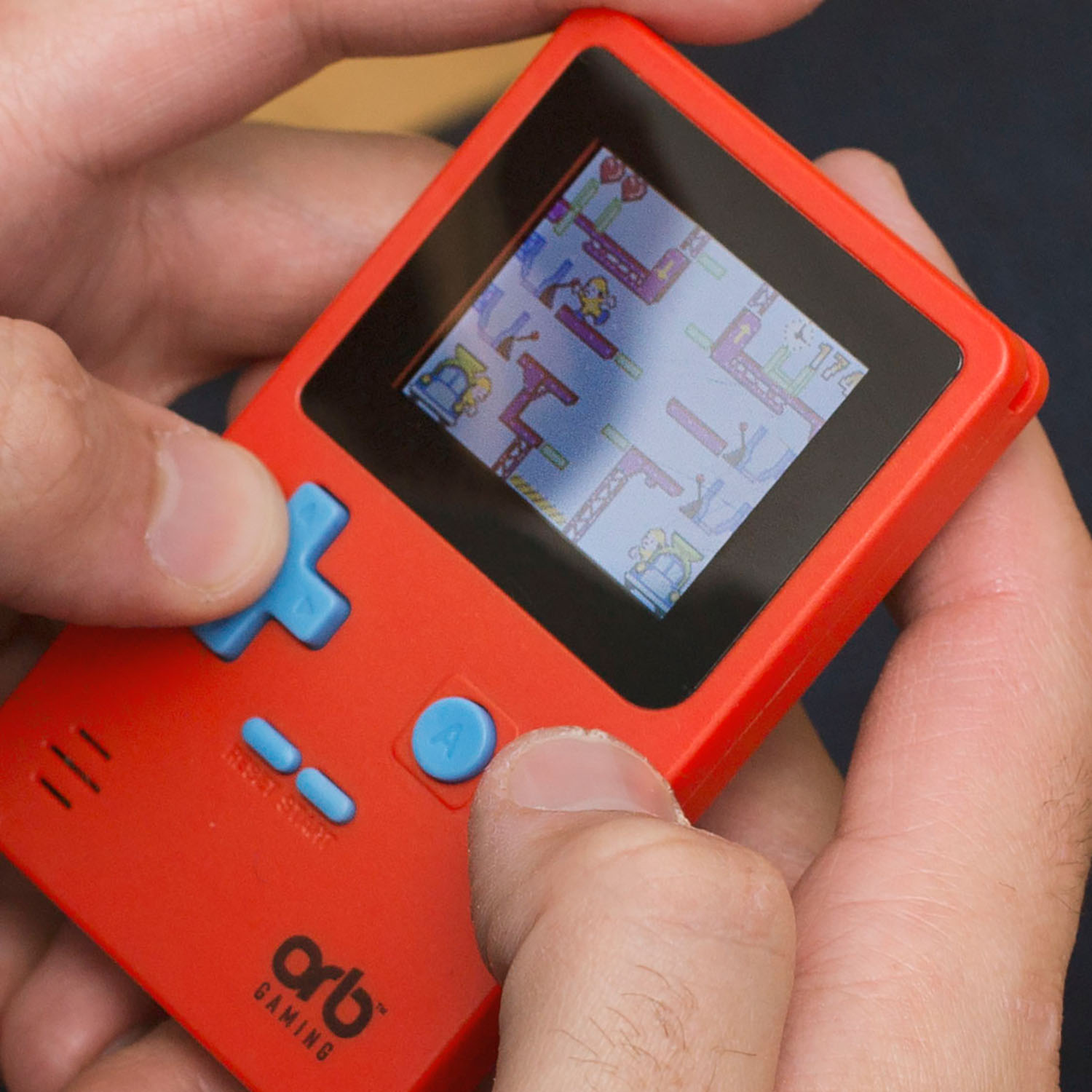 Mini handled game console
Now the goal of my next project was clear: create a similar handheld game console based on a STM32 microcontroller with a colorful screen and playable with a wireless Xbox Controller!
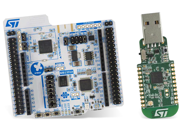 Nucleo WB55RG
Communication with a Xbox Controller
The first goal of this project is to connect the Xbox controller to my NUCLEO-WB55 board. The two communicate via BLE, but an appropriate driver should be written for the microcontroller to realize the connection and parse the controller inputs.
So before starting programming on my board, I need to know how the controller communicates with the Xbox driver on my PC.
To do that I am helped by two software tools:
- Wireshark on Windows/Linux, a network packet analysis software which can also capture and dissect BLE packets
- nRF Connect on Android, a generic BLE tool to scan, advertise, and communicate with a device.
Analyzing BLE packets via Wireshark
By connecting the controller to my PC and intercepting the BLE packets between the two devices, I can see all the frames sent by the controller when I realize a specific action (joystick moved, button pressed, trigger pushed, …).
For example, if I press the button B, the controller sends the following frame:
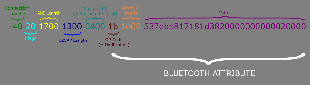 BLE packet received when button B is pressed
The most important part of this packet is the BLE attribute value, containing information about all the controller inputs. So, I filled an Excel document with the attribute values intercepted for each performed action and split them by byte. Note that to make it easier to reverse the protocol, I only do one action at a time. This way I am able to identify the purpose of each byte field in the BLE attribute value. Once all the packets captured, I deduced the following table:
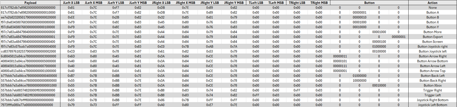 Table of packets for each action
Writing a Wireshark plugin
To check I didn’t make any mistakes and to better visualize the packets received, I developed a Wireshark dissector. Dissectors are meant to analyze some part of a packet’s data and I chose to integrate one into Wireshark via a plugin.
I did as follows:
- I downloaded the Wireshark source code and installed all the compilation tools
- I wrote my plugin code in C by following the Wireshark documentation on dissectors
- I recompiled the application and the plugin together
The Xbox controller protocol is then automatically detected when a BLE packet coming from the controller is received.
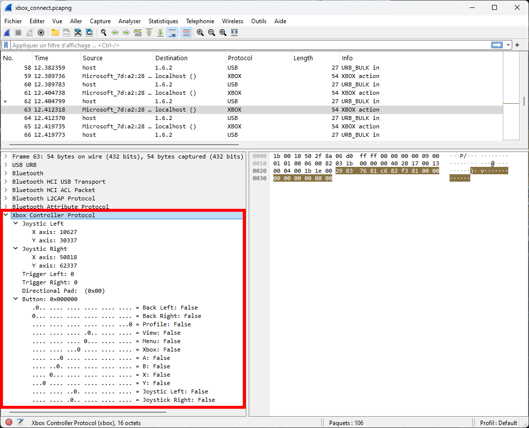 Wireshark with the Xbox Controller Dissector
My Xbox controller dissector for Wireshark is available on GitHub : https://github.com/nicopaulb/xbox-wireshark-dissector/tree/main
Analyzing BLE profile via nRF Connect
On my phone I launched nRF Connect to discover the BLE services and characteristics defined by the controller. I noticed it had a service called HID Report and guessed it was somehow using the HID protocol (designed for USB devices) over BLE.
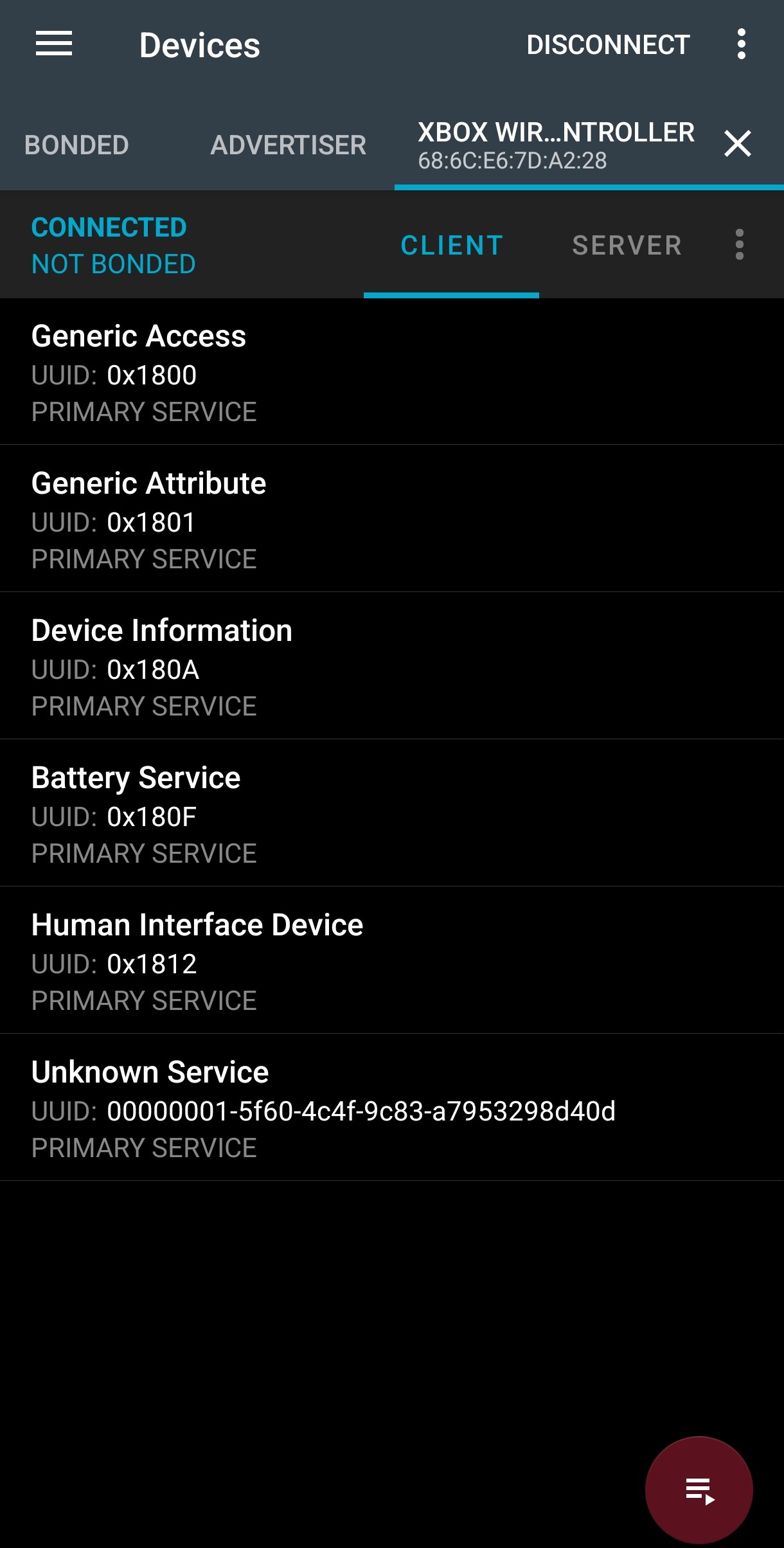 Xbox Controller on nRF Connect
After a quick search on internet, I found there is an official BLE profile called HID over GATT.
HID Protocol
The Human Interface Device (HID) protocol is a standard used by USB devices like keyboards, mice, game controllers, and touchscreens to communicate with an host system efficiently. This way the host operating system can include a built-in and standardized HID driver able to interpret any input devices.
During the device enumeration phase, a HID descriptor containing informations about the type of device and features (number of buttons, axes, keystrokes, …) is sent to the host. Also a report descriptor describing the format of data packets (reports) and how they should be interpreted can be asked by the host.
The HID host determines how often the device should send data by periodically polling the device at a fixed interval for input reports (key presses, mouse movement, …). The device can also receive output reports from the host to, for example, set LED indicators on a keyboard or enable controller rumble.
HOG (HID over GATT)
The HID over GATT profile is a way to use the HID protocol over BLE. It is based on GATT (Generic Attribute Profile) and defines an HID service with characteristics which are in turn based on the HID descriptors.
This service has the necessary characteristics and descriptors to emit notifications whenever a controller button is pressed/unpressed.
STM32WB55 programming
STM32CubeIDE
I kicked things off with STM32CubeIDE (eclipse based IDE). The nice part is that it doesn’t just provide a standard IDE (editor + debugger), but also includes CubeMX, the graphical code generator.
I quickly set up the required peripherals (clocks, debug UART, GPIOs, SPI and BLE), generated a clean baseline, and from there, I developed the application step by step, layering new functionality on top of that base.
Architecture
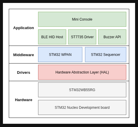 STM32WB55 Software Architecture
The software is divided in multiple layers of abstraction. I chose to show only the parts of the STM32 software stack that are actually used in this project:
- Hardware: At the base, the system runs on an STM32 Nucleo development board featuring the STM32WB55RG microcontroller. This chip integrates both an ARM Cortex-M4 for application code and a Cortex-M0+ dedicated to managing the Bluetooth Low Energy (BLE) radio.
- Drivers: On top of the hardware sits the Hardware Abstraction Layer (HAL), which provides a standardized API to configure and interact with the MCU’s peripherals (GPIOs, SPI, timers, etc.).
- Middleware: The middleware layer handles more complex system services. The STM32 WPAN is the wireless protocol stack that manages BLE communication and the STM32 Sequencer is a lightweight task scheduler that simplifies event-driven programming.
- Application: At the top sits my application, composed of:
- BLE HID Host: the module responsible for connecting to the Xbox controller, managing pairing, and parsing HID reports.
- ST7735 Driver: the display driver used to update the TFT screen.
- Buzzer API: the code to play sound effect using a piezo buzzer
- Mini Console: the main logic of the project, implementing the user interface, menu system, test screen, and games such as Snake.
BLE stack
The trickiest part, unsurprisingly, was the BLE stack. ST provides a broad API to manage connections, services, and characteristics. The documentation (notably AN5270) and example projects (notably BLE_P2PClient) were really useful here.
I implemented a state machine to handle the various asynchronous BLE events. The first step is to initialize the GAP and GATT protocols by calling all the necessary APIs. From there, multiple steps are required before the Xbox controller can be successfully paired. Most of these steps are summarized in the sequence diagram below:
sequenceDiagram
  participant A as Application<br>(STM32WB55)
  participant B as BLE Stack<br>(STM32WB55)
  participant X as Xbox Controller

  A <<->> B: Initialize GATT & GAP
  alt Search a Xbox Controller
    A ->>+ B: aci_gap_start_general_discovery_proc
    B ->> X: Start scan
    X ->> B: Advertising<br>(Complete Local Name = Xbox Wireless Controller)
    B ->> A: HCI_LE_ADVERTISING_REPORT_EVENT
    A ->> B: aci_gap_terminate_gap_proc
    B ->>- A: ACI_GAP_PROC_COMPLETE_EVENT
  end
  alt Connect to the found controller
    A ->> B: aci_gap_create_connection
    B ->> X: Connection request
    X ->> B: Link etablished
    B ->> A: HCI_LE_CONNECTION_COMPLETE_EVENT
  end
  alt Bound to the controller<br>('Just Work' method)
    A ->> B: aci_gap_send_pairing_req
    B ->> X: Pairing request
    X ->> B: Pairing response
    B ->> A: ACI_GAP_PAIRING_COMPLETE_EVENT
  end
    A <<->> B: GATT discovery procedure
Connection and pairing sequence diagram
To simplify, we can define three main states:
- Scanning: start a BLE scan to listen for advertising packets. The goal is to detect the Xbox controller by checking its Complete Local Name, available in its scan response. If the controller is not found (because it iss out of range or powered off), scanning restarts until it is detected.
- Connection: establish a link to the detected device.
- Pairing: pair using the Just Works method. This means the pairing process uses the legacy protocol with no secure mode, and MITM (Man-In-The-Middle) protection disabled. Since the controller provides no input capability (no keypad, display, or button for confirmation), it is impossible to use passcodes or keypress authentication.
Once paired, a second state machine takes over to discover the required GATT services and enable notifications (battery level, input reports, etc.), which allow the device to receive HID reports and battery level.
sequenceDiagram
  participant A as Application
  participant B as BLE Stack
  participant X as Xbox Controller

  A <<->> B: Initialize GATT & GAP
  A <<->> X: Connection & Pairing
  A ->> B: aci_gatt_disc_all_primary_services
  B ->> X: Discover primary services
  X ->> B: HID Service handle
  B ->> A: ACI_ATT_READ_BY_GROUP_TYPE_RESP_EVENT
  X ->> B: Battery Service handle
  B ->> A: ACI_ATT_READ_BY_GROUP_TYPE_RESP_EVENT

  alt Enabling HID Service notification
    A ->> B: aci_gatt_disc_all_char_of_service
    B ->> X: Discover characteristics of HID Service
    X ->> B: HID Service characteristic handle
    B ->> A: ACI_ATT_READ_BY_TYPE_RESP_EVENT
    A ->> B: aci_gatt_disc_all_char_desc
    B ->> X: Discover descriptors of HID Service characteristic
    X ->> B: HID Service descriptors handle
    B ->> A: ACI_ATT_FIND_INFO_RESP_EVENT
    A ->> B: aci_gatt_disc_all_char_of_service
    A ->> B: aci_gatt_write_char_desc
    B ->> X: Enable HID Report notification
    B ->> A: ACI_ATT_READ_RESP_EVENT
  end

  alt Enabling Battery Service notification
    B ->> X: Discover characteristics of Battery Service
    X ->> B: Battery Service characteristic handle
    B ->> A: ACI_ATT_READ_BY_TYPE_RESP_EVENT
    A ->> B: aci_gatt_disc_all_char_desc
    B ->> X: Discover descriptors of Battery Service characteristic
    X ->> B: Battery Service descriptors handle
    B ->> A: ACI_ATT_FIND_INFO_RESP_EVENT
    A ->> B: aci_gatt_write_char_desc
    B ->> X: Enable Battery Level notification
    B ->> A: ACI_ATT_READ_RESP_EVENT
  end

  alt Receiving notifications
    X ->> B: HID Report notification
    B ->> A: ACI_GATT_NOTIFICATION_VSEVT_CODE
    X ->> B: Battery Level notification
    B ->> A: ACI_GATT_NOTIFICATION_VSEVT_CODE
  end
GATT discovery sequence diagram
This layered structure makes it much easier to follow the BLE link lifecycle and to gracefully handle events such as disconnections or timeouts.
To make handling HID data easier, I defined a HID_Report_t structure based on the Wireshark Xbox Controller dissector made previously. This structure provides direct access to every button, joystick, and trigger value.
1
2
3
4
5
6
7
8
9
10
11
12
13
14
15
16
17
18
19
20
21
22
23
24
25
26
27
28
29
30
31
32
33
34
35
36
37
typedef struct __attribute__((packed))
{
  uint16_t JOY_LeftAxisX;                       // Left Joystick X, Value = 0 to 65535
  uint16_t JOY_LeftAxisY;                       // Left Joystick Y, Value = 0 to 65535
  uint16_t JOY_RightAxisX;                      // Right Joystick X, Value = 0 to 65535
  uint16_t JOY_RightAxisY;                     	// Right Joystick Y, Value = 0 to 65535
  uint16_t TRG_Left : 10;                       // Left Trigger, Value = 0 to 1023
  uint8_t  : 6;
  uint16_t TRG_Right : 10;                      // Right Trigger, Value = 0 to 1023
  uint8_t  : 6;
  uint8_t  HAT_Switch : 4;                      // Hat switch, Value = 1 to 8, Physical = (Value - 1) x 45 in degrees
#define HATSWITCH_NONE          0x00
#define HATSWITCH_UP            0x01
#define HATSWITCH_UPRIGHT       0x02
#define HATSWITCH_RIGHT         0x03
#define HATSWITCH_DOWNRIGHT     0x04
#define HATSWITCH_DOWN          0x05
#define HATSWITCH_DOWNLEFT      0x06
#define HATSWITCH_LEFT          0x07
#define HATSWITCH_UPLEFT        0x08
  uint8_t  : 4;
  uint8_t  BTN_A : 1;
  uint8_t  BTN_B : 1;
  uint8_t  BTN_RightJoystick : 1;
  uint8_t  BTN_X : 1;
  uint8_t  BTN_Y : 1;
  uint8_t  BTN_BackLeft : 1;
  uint8_t  BTN_BackRight : 1;
  uint8_t  : 2;
  uint8_t  BTN_View : 1;
  uint8_t  BTN_Menu : 1;
  uint8_t  BTN_Xbox : 1;
  uint8_t  BTN_LeftJoystick : 1;
  uint8_t  : 2;
  uint8_t  BTN_Profile : 1;
  uint8_t  : 7;
} HID_Report_t;
It is updated with each new BLE report event received from the controller (whenever a button is pressed or released).
TFT ST7735 Display Driver
The display is driven over SPI at 16 MHz, using the STM32 HAL SPI API in blocking mode. At this speed, refreshing a 160×128 pixel screen is fast enough that SPI never becomes a bottleneck in the software.
During initialization, the ST7735 registers are configured to operate in landscape mode, which adjusts the X and Y axes for memory access, and the display is set to 16-bit color mode. Before transmitting pixel data, an address window must be defined so the display knows exactly which region of the screen to update. This avoids having to refresh the entire framebuffer every time a single pixel or small area changes.
Functions to draw a single pixel, whole rectangle, text, or an image is available.
Here is a snippet of the ST7735_FillRectangle :
1
2
3
4
5
6
7
8
9
10
11
12
13
14
15
16
17
18
19
20
21
void ST7735_FillRectangle(uint16_t x, uint16_t y, uint16_t w, uint16_t h, uint16_t color)
{
	uint16_t line[ST7735_WIDTH] = {0};
	uint8_t pixel[] = { color >> 8, color & 0xFF };

	if((x >= ST7735_WIDTH) || (y >= ST7735_HEIGHT)) return;
	if((x + w - 1) >= ST7735_WIDTH) w = ST7735_WIDTH - x;
	if((y + h - 1) >= ST7735_HEIGHT) h = ST7735_HEIGHT - y;

	ST7735_SELECT();
	ST7735_SetAddressWindow(x, y, x+w-1, y+h-1);

	for(x = 0; x < w; ++x)
		memcpy(line + x, pixel, sizeof(pixel));

	HAL_GPIO_WritePin(ST7735_DC_GPIO_Port, ST7735_DC_Pin, GPIO_PIN_SET);
	for(y = h; y > 0; y--)
		HAL_SPI_Transmit(&ST7735_SPI_PORT, (uint8_t*) line, w * sizeof(pixel), HAL_MAX_DELAY);

	ST7735_UNSELECT();
}
All related code is implemented in st7735.c, which provide the configuration and drawing functions.
Menu and navigation
Menu handling and navigation are implemented through another state machine, where each screen has its own state along with two transitions: Enter and Exit. All screens features a common header bar that displays the current page name along with the controller’s battery level.
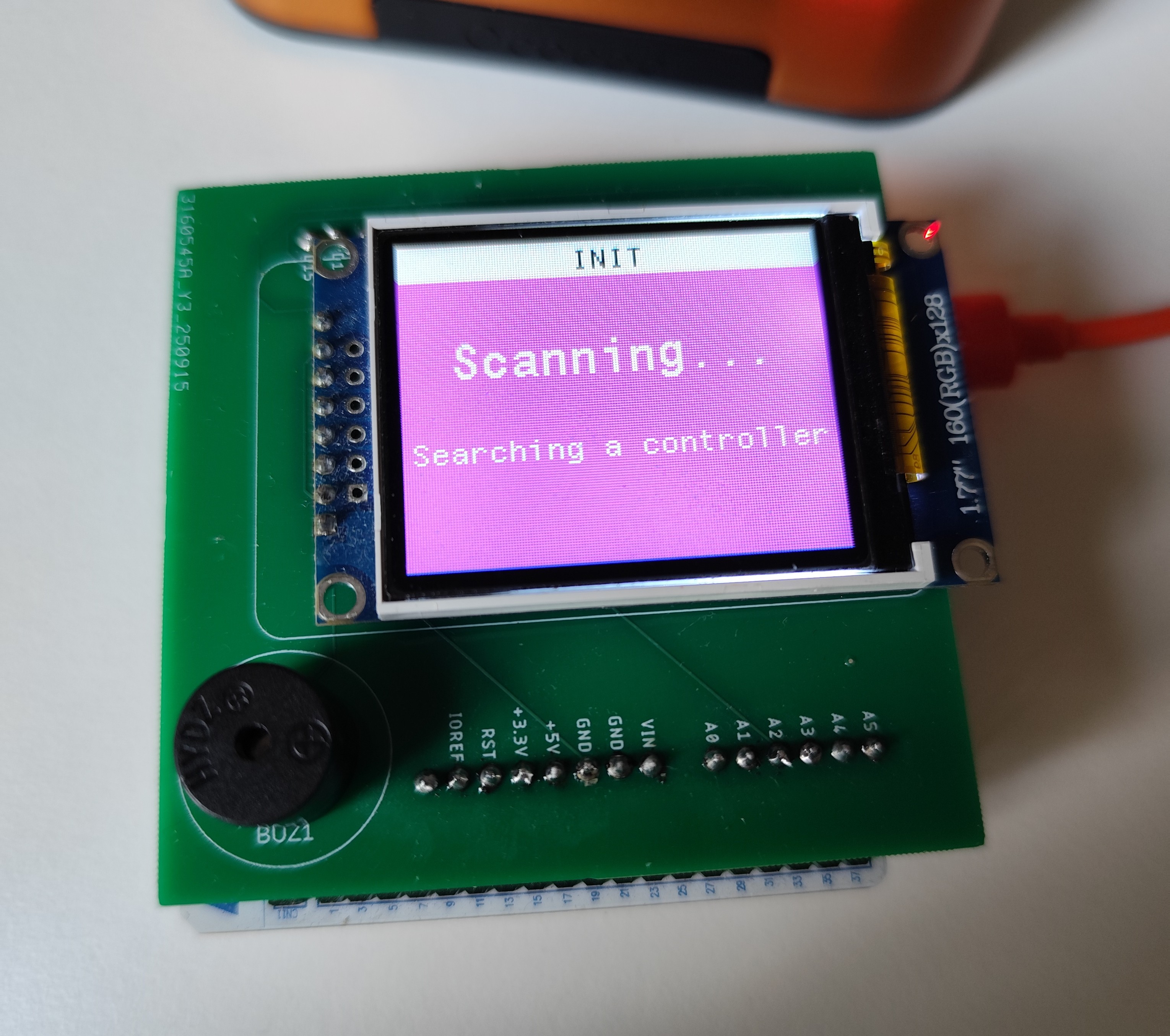
At startup, the display shows the different connection steps described earlier in the BLE stack section.
 Connection Screen
Once in the menu, navigation is done using the arrow keys to move between items, while the A button is used to confirm a selection.
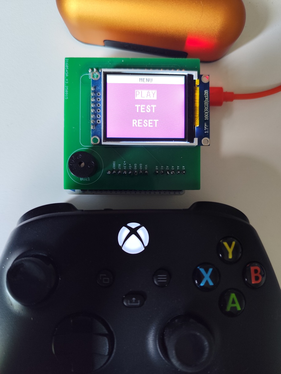 Menu Screen
Testing screen
The first screen I implemented was a test screen, designed to verify that communication with the controller was functioning correctly and that the HID report was being properly parsed. It simply displays which buttons are currently pressed on the controller.
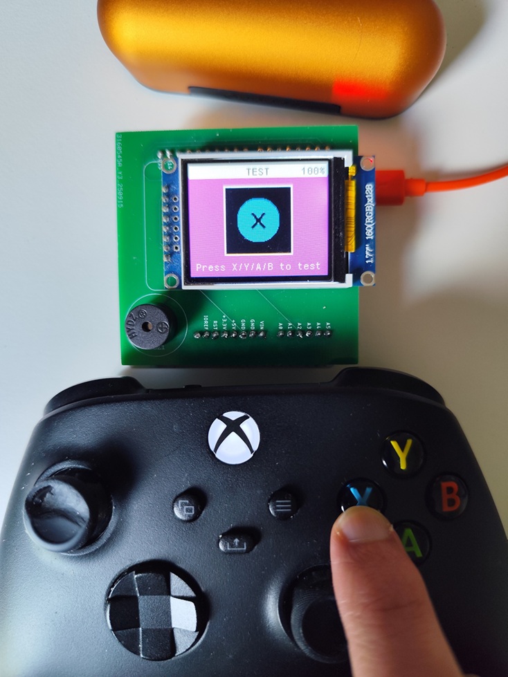 Test Screen
Snake screen
After the test screen, I implemented a simple Snake game. I chose Snake for a few reasons: it’s a very famous game that almost everyone recognizes, and its mechanics are relatively simple to implement. The game logic doesn’t require complex physics or graphics, which makes it ideal for a first game.
Snake also provides a practical way to test the controller input in a dynamic scenario: arrow keys, joysticks or A/X/Y/B buttons from the Xbox controller can be mapped directly to the snake’s movement, allowing me to validate that the HID reports are parsed and processed correctly while updating the display in real time.
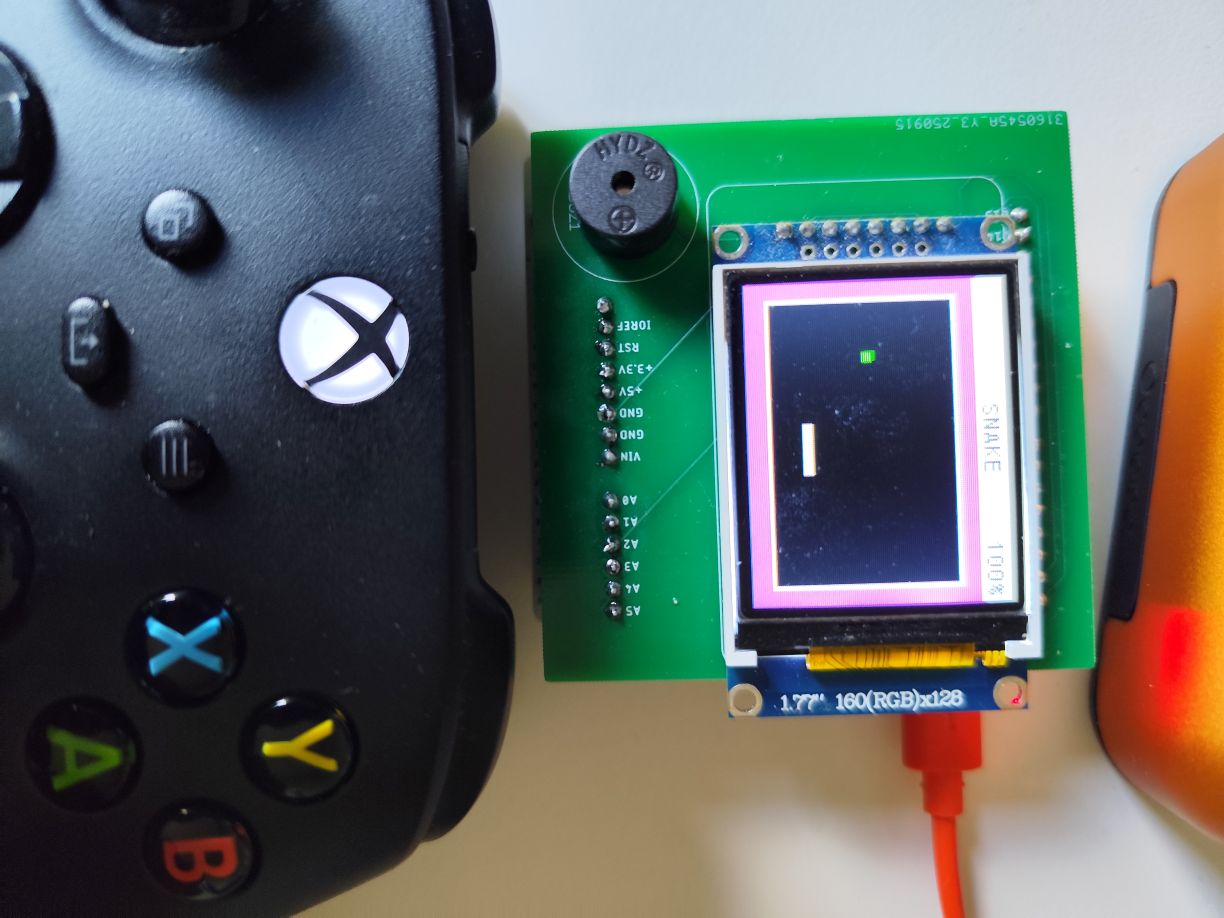 Snake Screen
The game is structured around a grid-based system, where the screen is divided into cells (5×5 pixels each) and the snake occupies a sequence of these cells. The display area for the game is centered on the screen, with a small border to visually frame the playing field.
The screen follows the usual Enter → Current → Exit pattern of the application state machine.
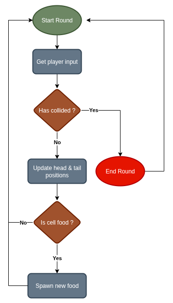 Snake Game Flow
In the Current state, the main game loop runs every BASE_TICK_TIME (default 200 ms). Each tick performs several key operations:
- Player input: Arrow keys, joystick axes, or buttons (A/B/X/Y) from the Xbox controller are interpreted via the HID report to determine the snake’s direction. The system prevents the snake from reversing into itself.
- Collision detection: If the snake collides with a wall or itself, a Game Over screen is displayed and the round ends. The player is prompted to press B to play again.
- Movement update: If no collision occurs, the tail of the snake is removed and a new head is drawn in the chosen direction.
- Food spawning: If the snake eats the food, a new one is spawned randomly in an empty cell, and the snake’s body length increases.
Here a snippet of the main game loop :
1
2
3
4
5
6
7
8
9
10
11
12
13
14
15
16
17
18
19
20
21
22
23
24
25
26
27
void Stage_Snake_Handle(HID_Report_t *report, uint8_t battery) {
	if (report->BTN_B && !round_running) {
		start_round();
	}

	if (report->BTN_Xbox) {
		round_running = false;
		App_Set_Stage(STAGE_SNAKE_EXIT);
	}

	if (round_running) {
		static long long last_tick = 0;
		long long cur_tick = HAL_GetTick();
		coord_t dir = get_direction(report);

		if (cur_tick - last_tick > BASE_TICK_TIME) {
			last_tick = cur_tick;
			coord_t new_head = { head.x + dir.x, head.y + dir.y };
			// Check for collision
			if (is_wall_collided(&new_head) || is_body_collided(&new_head)) {
				end_round();
			} else {
				move_snake(&new_head);
			}
		}
	}
}
The entire game area is tracked in a grid array, where each cell can be empty, occupied by the snake, or contain food. The head and tail are tracked separately, which simplifies updates.
However, finding the new tail position after each tick requires an additional mechanism. To solve this, every snake body cell is assigned a number that increases at each tick. The oldest cell (the tail) has the smallest number, while the head always has the largest. To find the new tail, the system simply looks for the adjacent cell with the number +1, making tail updates both reliable and efficient.
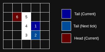 Tail-Finding Mechanism
Also to optimize performance and ensure smooth updates, only the tail, head, and food cells are redrawn using small rectangles, rather than refreshing the entire display.
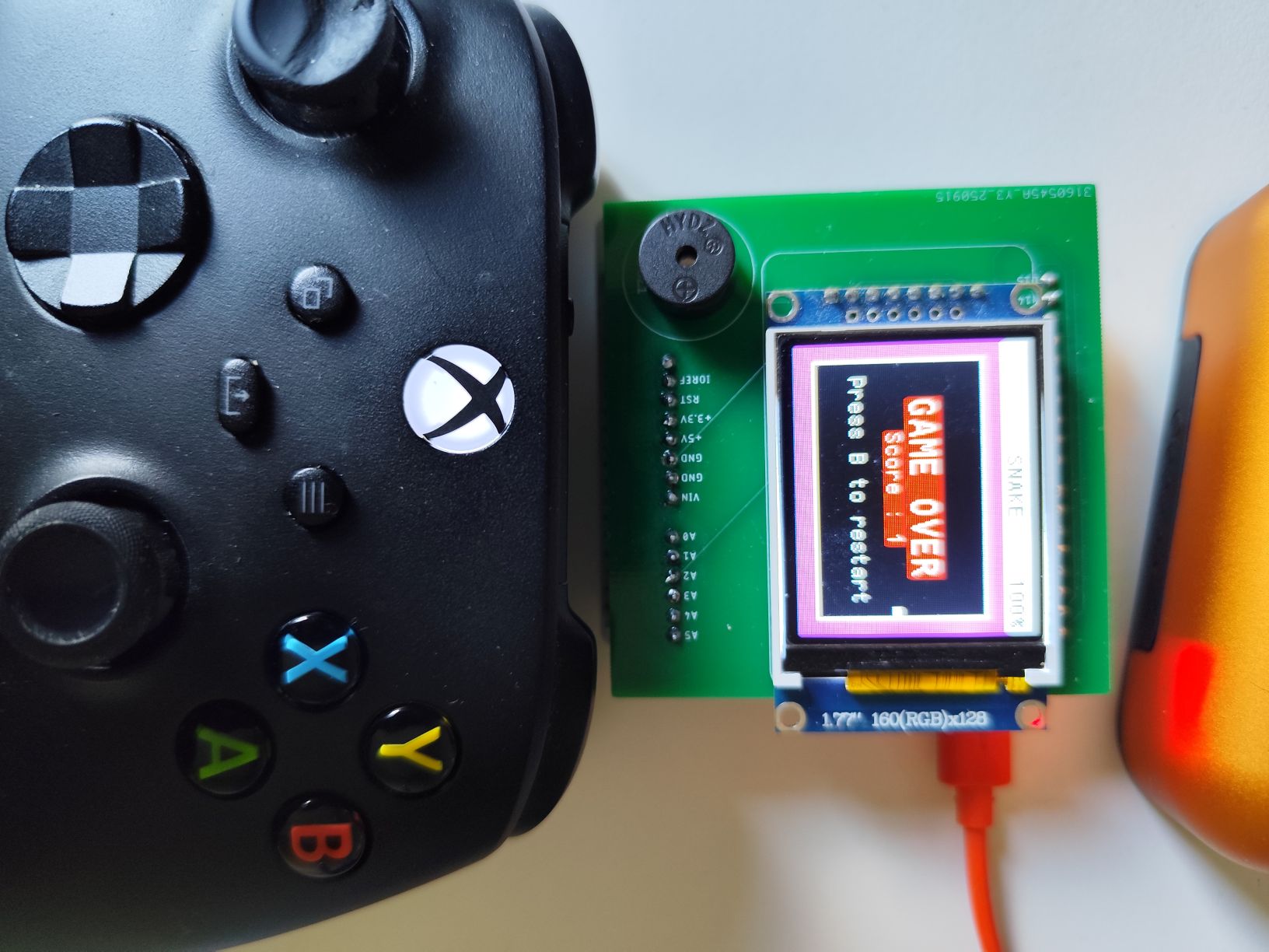 Snake Game Over Screen
The Snake logic is implemented in stage_snake.c
Playing sound
To complement the display, I added basic sound feedback using a passive buzzer connected to the microcontroller. The buzzer is controlled via a PWM signal generated by one of the STM32 timers, allowing simple tones to be produced at different frequencies.
To keep playback non-blocking, a second STM32 timers takes care of timing each note. It updates the PWM frequency after the desired duration, letting the buzzer play short jingles or feedback sounds without holding up the main application.
The core of the buzzer logic is the Buzzer_Play_Tone in buzzer.c function that sets up the PWM frequency (for pitch) and a second timer (for duration). When called, it configures the timers and starts them:
1
2
3
4
5
6
7
8
9
10
11
static void Buzzer_Play_Tone(uint16_t frequency, uint16_t duration) {
	__HAL_TIM_SET_COUNTER(&BUZZER_TIM2_HANDLE, duration);

	if (frequency != 0) {
		__HAL_TIM_SET_PRESCALER(&BUZZER_TIM_HANDLE, TIMR_PRS(frequency));
		HAL_TIM_PWM_Start(&BUZZER_TIM_HANDLE, TIM_CHANNEL_1);
	}

	__HAL_TIM_ENABLE_IT(&BUZZER_TIM2_HANDLE, TIM_IT_UPDATE);
	__HAL_TIM_ENABLE(&BUZZER_TIM2_HANDLE);
}
When the duration timer (TIM2) expires, it raises an interrupt. Inside the callback, the PWM is stopped and, if more tones are queued, the next one is started automatically:
1
2
3
4
5
6
7
8
9
void HAL_TIM_PeriodElapsedCallback(TIM_HandleTypeDef *htim) {
	if (htim->Instance == TIM2) {
		HAL_TIM_PWM_Stop(&BUZZER_TIM_HANDLE, TIM_CHANNEL_1);
		tone_id++;
		if (tone_id < tone_buf.size) {
			Buzzer_Play_Tone(tone_buf.frequency[tone_id], tone_buf.duration[tone_id]);
		}
	}
}
Each melody is represented by two parallel arrays: one holding the frequencies (in hertz) and the other the durations (in milliseconds). This makes it straightforward to describe short jingles or sound effects in a compact form.
For example, the boot-up jingle is defined as:
1
2
static const uint16_t boot_freqs[] = { 523, 659, 784, 1047 };
static const uint16_t boot_durations[] = { 150, 150, 150, 300 };
Here, the buzzer plays a rising sequence of notes (C5 → E5 → G5 → C6), with each note lasting between 150 and 300 milliseconds.
The Buzzer logic is implemented in buzzer.c
Sound is used at key moments to make the interface more engaging:
- Short melody on startup
- Beeps when navigating through the menu
- Sound effects during gameplay (for example, when the snake eats food or when a game-over occurs)
Even with such a simple component, this adds an extra layer of interactivity to the project and makes it feel much closer to a real console.
PCB
For this project, I chose to only design a Nucleo-WB55 hat, featuring the TFT display and a passive buzzer. This custom board is convenient for prototyping since it can be directly plugged into the Nucleo-WB55 development board.
Layout
The PCB was designed using Fusion 360 (formerly Eagle), where I created the necessary component schematics and footprints.
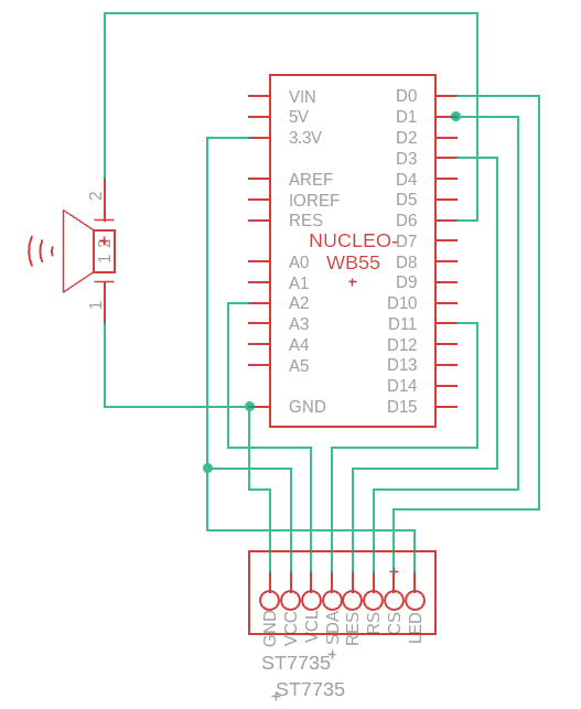 Schematic
From there, I completed the PCB layout and routed the connections, ensuring compact placement of the screen and buzzer.
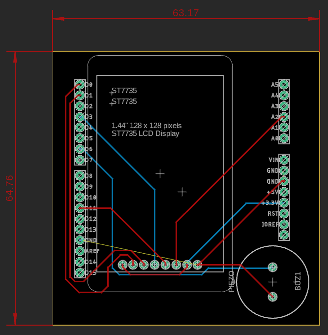 PCB layout
The final design was manufactured through JLCPCB.
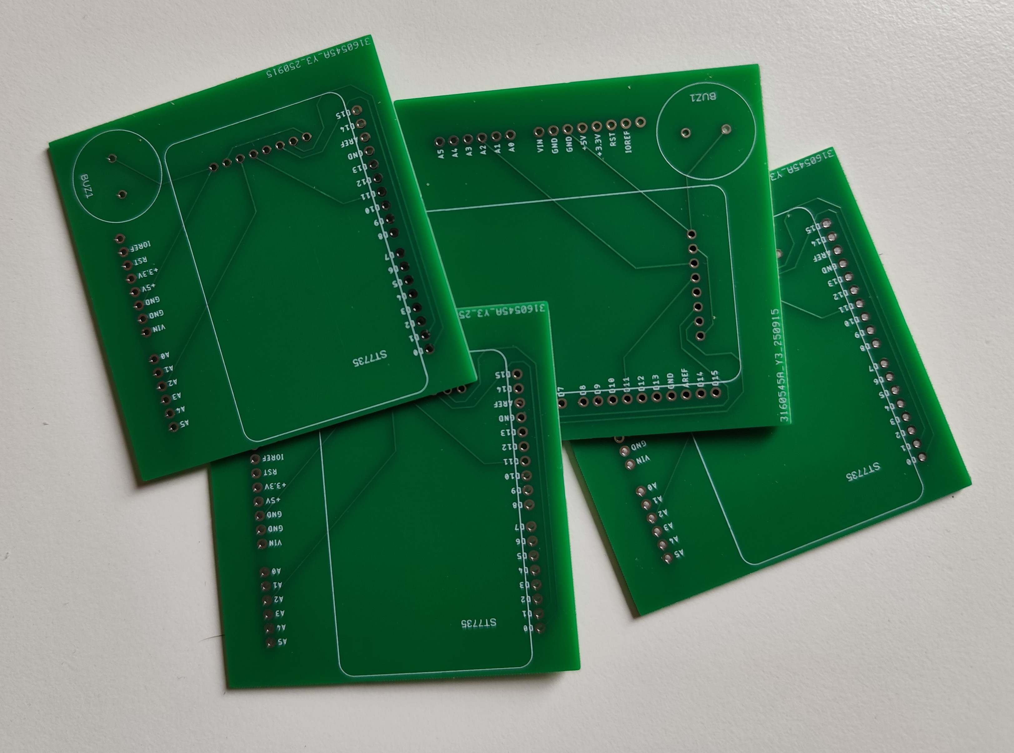 PCB Photo
Once the PCB arrived, I soldered the required components:
- Male header pins
- ST7735 TFT display
- Passive buzzer
After soldering, the hat was mounted directly on top of the Nucleo-WB55 board. This made the setup modular, allowing quick iteration during software development while keeping the hardware tidy and reliable.
 PCB mounted on the Nucleo
Demo
Future improvement
While the current prototype already delivers a functional mini console, there are several ideas for future enhancements:
- New games: expand beyond Snake with different and more complex titles
- Controller rumble support: use the Xbox controller’s vibration motors to provide haptic feedback
- Custom enclosure: design and 3D-print a case to make the console more durable and visually polished.